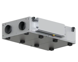
CX3000
Air handling unit
Compact and low-noise ceiling-mounted units, an ideal solution for optimal use of space

Compact and low-noise ceiling-mounted units, an ideal solution for optimal use of space
New
Refurbishment
Non-residential buildings
Schools
6 CX3000 models from 500 to 3 300 m3/h
Counterflow monoblock units
free-hanging design with double plate panels
External finish: Aluzinc AZ185: corrosion class C4
50 mm mineral wool insulation, density 70 kg/m3
EN1886 values: D2, L2/L2, T2, TB3, F9
EC motor with high efficiency B wheel Metal/Composite
Easy service and maintenance access: hinged doors or sliding rails for the doors as optional accessories
High-performance heat exchanger
Modulating bypass
Filter options for optimised air quality.: panel filter ISO ePM10 50% (M5) or ISO ePM1 50% (F7) standard filters, option for ISO ePM1 80% (F9)
EXcon Control System
Constant speed
multi-speed
Constant pressure
0–10 V
Configuration and monitoring via
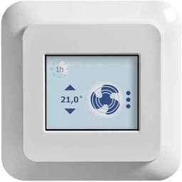
HMI cable for remove control
option: Web server and BMS Communication via Modbus RTU/RS485, BACnet MSTP/BACnet IP protocol
option: Web server and BMS Communication via bridge to Modbus TCP/IP or LON protocol
EXcon Control System:
Constant speed,
Constant airflow,
Constant pressure,
Air measurement control CO2/VOC sensor (0–10V signal). - Controlled pressure,
Built-in clock: operation hours can be controlled by means of a timer,
Remote control system via cable,
BMS Communication via Modbus RTU and Bacnet TCP/IP protocols.
- Constant air speed (CAV). - Variable air speed (VAV).
Airflow controlled - demand controlled (DCV) using CO2,/VOC sensor (0–10V signal) ,
Option: Built-in web server,
Option: BMS communication via Modbus RTU/RS485, Modbus TCP/IP, BACnet, MSTP/BACnet IP.
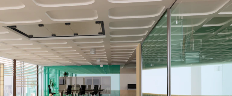
Indoor above (false ceiling)
Round or rectangular duct mounting
Right and left variants
| Variants | Insulation density (kg/m³) | Thickness of insulation (mm) | Available filters | Connection direction | Type of exchanger | Total pressure (Pa) | RPM during optimal operating point |
|---|---|---|---|---|---|---|---|
| CX3010 Left | 70 kg/m³ | 50 mm | Standard ISO ePM10 50% (M5) and ISO ePM1 50% (F7) filter, Accessory: ISO ePM1 80% (F9) filter box | Ceiling | Counterflow | 451 Pa | |
| CX3010 Right | 70 kg/m³ | 50 mm | Standard ISO ePM10 50% (M5) and ISO ePM1 50% (F7) filter, Accessory: ISO ePM1 80% (F9) filter box | Ceiling | Counterflow | 451 Pa | |
| CX3020 Left | 70 kg/m³ | 50 mm | Standard ISO ePM10 50% (M5) and ISO ePM1 50% (F7) filter, Accessory: ISO ePM1 80% (F9) filter box | Ceiling | Counterflow | 645 Pa | |
| CX3020 Right | 70 kg/m³ | 50 mm | Standard ISO ePM10 50% (M5) and ISO ePM1 50% (F7) filter, Accessory: ISO ePM1 80% (F9) filter box | Ceiling | Counterflow | 645 Pa | |
| CX3030 Left | 70 kg/m³ | 50 mm | Standard ISO ePM10 50% (M5) and ISO ePM1 50% (F7) filter, Accessory: ISO ePM1 80% (F9) filter box | Ceiling | Counterflow | 555 Pa | |
| CX3030 Right | 70 kg/m³ | 50 mm | Standard ISO ePM10 50% (M5) and ISO ePM1 50% (F7) filter, Accessory: ISO ePM1 80% (F9) filter box | Ceiling | Counterflow | 555 Pa | |
| CX3040 Left | 70 kg/m³ | 50 mm | Standard ISO ePM10 50% (M5) and ISO ePM1 50% (F7) filter, Accessory: ISO ePM1 80% (F9) filter box | Ceiling | Counterflow | 654 Pa | |
| CX3040 Right | 70 kg/m³ | 50 mm | Standard ISO ePM10 50% (M5) and ISO ePM1 50% (F7) filter, Accessory: ISO ePM1 80% (F9) filter box | Ceiling | Counterflow | 654 Pa | |
| CX3050 Left | 70 kg/m³ | 50 mm | Standard ISO ePM10 50% (M5) and ISO ePM1 50% (F7) filter, Accessory: ISO ePM1 80% (F9) filter box | Ceiling | Counterflow | 770 Pa | |
| CX3050 Right | 70 kg/m³ | 50 mm | Standard ISO ePM10 50% (M5) and ISO ePM1 50% (F7) filter, Accessory: ISO ePM1 80% (F9) filter box | Ceiling | Counterflow | 770 Pa | |
| CX3060 Left | 70 kg/m³ | 50 mm | Standard ISO ePM10 50% (M5) and ISO ePM1 50% (F7) filter, Accessory: ISO ePM1 80% (F9) filter box | Ceiling | Counterflow | 770 Pa | |
| CX3060 Right | 70 kg/m³ | 50 mm | Standard ISO ePM10 50% (M5) and ISO ePM1 50% (F7) filter, Accessory: ISO ePM1 80% (F9) filter box | Ceiling | Counterflow | 770 Pa | 3.105 |
| Variants | ECO efficiency level during optimal operating point | Efficiency level requirements | Max. Total efficiency (A-D) (%) | EC motor |
|---|---|---|---|---|
| CX3010 Left | 74,5N | 62N (2015) | 48,5 % | With motor controller (VSD) |
| CX3010 Right | 74,5N | 62N (2015) | 48,5 % | With motor controller (VSD) |
| CX3020 Left | 73N | 62N (2015) | 51,2 % | With motor controller (VSD) |
| CX3020 Right | 73N | 62N (2015) | 51,2 % | With motor controller (VSD) |
| CX3030 Left | 83,6N | 62N (2015) | 65,5 % | With motor controller (VSD) |
| CX3030 Right | 83,6N | 62N (2015) | 65,5 % | With motor controller (VSD) |
| CX3040 Left | 82,6N | 62N (2015) | 65,6 % | With motor controller (VSD) |
| CX3040 Right | 82,6N | 62N (2015) | 65,6 % | With motor controller (VSD) |
| CX3050 Left | 85,9N | 62N (2015) | 69,5 % | With motor controller (VSD) |
| CX3050 Right | 85,9N | 62N (2015) | 69,5 % | With motor controller (VSD) |
| CX3060 Left | 85,9N | 62N (2015) | 69,5 % | With motor controller (VSD) |
| CX3060 Right | 85,9N | 62N (2015) | 69,5 % | With motor controller (VSD) |
| Variants | Fluid temperature (air) | Ambient temperature range |
|---|---|---|
| CX3010 Left | -20°C....+35°C | -40°C....+40°C |
| CX3010 Right | -20°C....+35°C | -40°C....+40°C |
| CX3020 Left | -20°C ....+35°C | -40°C....+40°C |
| CX3020 Right | -20°C ....+35°C | -40°C....+40°C |
| CX3030 Left | -20°C ....+35°C | -40°C....+40°C |
| CX3030 Right | -20°C ....+35°C | -40°C....+40°C |
| CX3040 Left | -20°C ....+35°C | -40°C....+40°C |
| CX3040 Right | -20°C ....+35°C | -40°C....+40°C |
| CX3050 Left | -20°C ....+35°C | -40°C....+40°C |
| CX3050 Right | -20°C ....+35°C | -40°C....+40°C |
| CX3060 Left | -20°C ....+35°C | -40°C....+40°C |
| CX3060 Right | -20°C ....+35°C | -40°C....+40°C |


| Variants | A (mm) | B (mm) | C (mm) | Ø connection (mm) | Weight (kg) |
|---|---|---|---|---|---|
| CX3010 Left | 1500 mm | 900 mm | 370 mm | 200 mm | 125 kg |
| CX3010 Right | 1500 mm | 900 mm | 370 mm | 200 mm | 125 kg |
| CX3020 Left | 1600 mm | 1150 mm | 400 mm | 250 mm | 164 kg |
| CX3020 Right | 1600 mm | 1150 mm | 400 mm | 250 mm | 164 kg |
| CX3030 Left | 1800 mm | 1500 mm | 480 mm | 230 kg | |
| CX3030 Right | 1800 mm | 1500 mm | 480 mm | 230 kg | |
| CX3040 Left | 2000 mm | 1650 mm | 565 mm | 286 kg | |
| CX3040 Right | 2000 mm | 1650 mm | 565 mm | 286 kg | |
| CX3050 Left | 2100 mm | 1650 mm | 580 mm | 325 kg | |
| CX3050 Right | 2100 mm | 1650 mm | 580 mm | 325 kg | |
| CX3060 Left | 2250 mm | 1970 mm | 580 mm | 370 kg | |
| CX3060 Right | 2250 mm | 1970 mm | 580 mm | 370 kg |
| Variants | Max. airflow (m³/h) | Max. airflow ErP (m³/h) | Minimum airflow |
|---|---|---|---|
| CX3010 Left | 475 m³/h | 475 m³/h | 55 |
| CX3010 Right | 475 m³/h | 475 m³/h | 55 |
| CX3020 Left | 990 m³/h | 990 m³/h | 101 |
| CX3020 Right | 990 m³/h | 990 m³/h | 101 |
| CX3030 Left | 1680 m³/h | 1600 m³/h | 152 |
| CX3030 Right | 1680 m³/h | 1600 m³/h | 152 |
| CX3040 Left | 2150 m³/h | 2070 m³/h | 215 |
| CX3040 Right | 2150 m³/h | 2070 m³/h | 215 |
| CX3050 Left | 2820 m³/h | 2810 m³/h | 282 |
| CX3050 Right | 2820 m³/h | 2810 m³/h | 282 |
| CX3060 Left | 3395 m³/h | 3280 m³/h | 305 |
| CX3060 Right | 3395 m³/h | 3280 m³/h | 305 |
| Variants | Max. exchanger output (%) | Max. current absorbed (kW) |
|---|---|---|
| CX3010 Left | 94 % | 3,4 kW |
| CX3010 Right | 94 % | 3,4 kW |
| CX3020 Left | 94 % | 4,2 kW |
| CX3020 Right | 94 % | 4,2 kW |
| CX3030 Left | 94 % | 5 kW |
| CX3030 Right | 94 % | 5 kW |
| CX3040 Left | 94 % | 7 kW |
| CX3040 Right | 94 % | 7 kW |
| CX3050 Left | 94 % | 4 kW |
| CX3050 Right | 94 % | 4 kW |
| CX3060 Left | 94 % | 4 kW |
| CX3060 Right | 94 % | 4 kW |
| Variants | Frequency (Hz) | Max. power of electrical coil 1 (kW) | Max. electrical output of unit (kW) | Voltage (V) | Maximum current - unit (A) | Max. power of electrical coil 2 |
|---|---|---|---|---|---|---|
| CX3010 Left | 50 Hz | 3 kW | 0,452 kW | 1x230 V | 3,4 A | |
| CX3010 Right | 50 Hz | 3 kW | 0,452 kW | 1x230 V | 3,4 A | |
| CX3020 Left | 50 Hz | 5 kW | 0,56 kW | 1x230 V | 4,2 A | |
| CX3020 Right | 50 Hz | 5 kW | 0,56 kW | 1x230 V | 4,2 A | |
| CX3030 Left | 50 Hz | 4 kW | 1,12 kW | 1x230 V | 5,0 A | 8 |
| CX3030 Right | 50 Hz | 4 kW | 1,12 kW | 1x230 V | 5,0 A | 8 |
| CX3040 Left | 50 Hz | 5,5 kW | 1,58 kW | 1x230 V | 7,0 A | 11 |
| CX3040 Right | 50 Hz | 5,5 kW | 1,58 kW | 1x230 V | 7,0 A | 11 |
| CX3050 Left | 50 Hz | 7 kW | 2,32 kW | 3x400 V | 4,0 A | 14 |
| CX3050 Right | 50 Hz | 7 kW | 2,32 kW | 3x400 V | 4,0 A | 14 |
| CX3060 Left | 50 Hz | 9 kW | 2,32 kW | 3x400 V | 4,0 A | 18 |
| CX3060 Right | 50 Hz | 9 kW | 2,32 kW | 3x400 V | 4,0 A | 18 |

The cabinet is made of 0.8-mm galvanised steel corrosion class C4 in accordance with EN/ISO12944-2and insulated with 50 mm mineral wool. This results in low noise emissions to the surrounding environment.

Heat recovery occurs via a counterflow heat exchanger in aluminium with a very high efficiency. (Without condensation 80-85%, with condensation up to 95%). The integrated bypass has multiple functions:
When heat recovery is not desired, the outdoor air is directed outside the heat exchanger
If night cooling is desired, the outdoor air is directed outside the heat exchanger
In case of freezing of the heat exchanger, the outdoor air is directed outside the heat exchanger so that the exchanger can thaw. The supply air (outdoor air) then requires extra heating capacity via the postheater – the reheater is a prerequisite for the system to function continuously
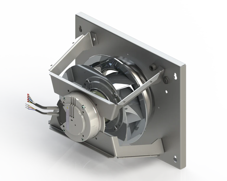
The motors are of type EC and are extremely efficient. They comply with the requirements of the Ecodesign Directive.

CX3000 is equipped with an optimised centrifugal impeller with backward curved blades.
The wheel is made from a composite material and its shape provides great performance with low energy consumption.

CX3000 accessories
HW: Water heating coil for integration
P-HE: Duct-mounted electric preheating coil
A-HE: Duct-mounted electric heating coil
CW: Duct-mounted cooling/heating coil
Find technical data for the different heating and cooling/heating coils under each size.

The easily accessible connection box with built-in isolator switch and control fuses ensures easy access for connection and adjustment. Read more about electrical connection in the guide “Electrical guide for CX3000”

Panel filters for supply air and extract air– the filters are easy to replace.
The filters are available in the following filter classes:
Extract air: ePM10 50% (M5)
Supply air: ePM1 50% (F7)
See filter size under Filters for the individual CX size.

Extra filter housing for improved indoor climate It is possible to insert a duct-mounted filter housing after the unit on the supply air side.
Filter class: ePM1 80%(F9)
The compact unit is designed in accordance with German hygiene standard VDI6022, which ensures units are accessible for service and the formation of mould or other bacteria that could negatively impact air quality is prevented. Read more about this standard in the VDI section under certificates further down this page.

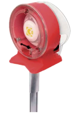
The CX3000 is equipped with hinged doors that can be opened on both sides. If the location and space make it difficult to fit the suspended doors, we can supply rails (accessories) that are mounted under the unit so that the doors can be dismantled and placed on the rails while the unit is being serviced.

All CX3000 must be commissioned to ensure that the unit is correctly set up. This is done via a Windows program, CX3000 Configurator, which can be downloaded via a link at the top of the page.
Configuration takes place via a LAN cable connected to the Excon-Master-Module and a PC.

All CX3000 units are available with integral EXcon control systems for optimum control of the indoor climate in practically every application area.
EXcon control systems can be used for controlling airflows, heating, cooling, etc. The operating program is configured for how and when the control system will switch between the integral functions.
The operation of the unit is constantly monitored by the EXcon control system, which protects the counterflow heat exchanger against icing, against frost damage to the water heating and cooling coils, and against overheating of the electric heating coils.
Using the 3 integrated protocols BACnet IP, Modbus TCP/IP or Modbus RTU, it is easy to monitor virtually all parameters via BMS, as well as control the operation of the system.
With the EXcon control system’s many functions, it is possible to optimise and adapt the system's operation to achieve the most energy-efficient regulation by e.g. compensating for the outdoor temperature, changing the regulation to suit the summer or winter season, limit active cooling or heating, automatically lower the temperature setpoint and cool down the building at night during the warm summer periods.
Integrated functions in the EXcon control system for CX3000:
Automatic temperature reduction in low-speed operation
Alarm and data log
Control using a day, week or year plan
Extended operation for set periods
External switch between regulation levels
Alarm email (requires local mail server)
Summer night cooling
Outdoor air temperature compensation
Automatic summer/winter time changeover
Filter monitoring via pressure measurement
Portal solution with total monitoring of 5 systems
Connection to CTS/BMS via BACnet IP, Modbus TCP or RTU (over 900 registers)
2 configurable digital inputs for:
Fire alarm (factory setting)
AHU emergency stop
Manual override for Low speed
Manual override for Medium speed
Manual override for High speed (factory setting)
Frost alarm
External start/stop
2 configurable outputs for:
Operating signal (factory setting)
An alarm (factory setting)
B alarm
Alarm reset
Summer night cooling active
Summer season active
The EXcon control system offers various regulation options, where the larger CX models can also offer pressure-controlled regulation. Below is an overview of the options:
CX3010-3020:
Temperature-controlled de-icing with modulating bypass damper
Static monitoring of filter pressure loss
Operation of electric heating coils is released using thermostat, which protects against overheating at low airflows.
Regulation options:
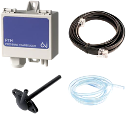
Constant pressure (requires pressure transmitters as accessory)
Constant CO2
Constant motor speed
Temperature regulation:
Constant supply air
Constant room
Constant extract air
Temperature difference between supply air and extract air
Heating and cooling coils:
Preheating coil, electrical
Heating coil, electrical
Heating coil, water
Cooling coil, water
Cooling-heating coil
Automatic frost protection of water heating coil and cooling/heating coil
3 regulation steps - Low, Medium and High speed
CX3030-3060:
Airflow measurement, adjustable using K factor
Dynamic pressure-controlled de-icing with ON/OFF bypass damper in relation to hours
Option of selecting Temperature controlled de-icing with modulating bypass damper
Dynamic monitoring of filter pressure loss in relation to airflow
Option to select static monitoring of filter pressure loss
Operation of electric heating coils in relation to airflow
Regulation options:
Constant airflow
Constant pressure (requires pressure transmitters as accessory)
Constant CO2
Constant motor speed
Dynamic pressure (requires pressure transmitters as accessory)
Temperature regulation:
Constant supply air
Constant room
Constant extract air
Temperature difference between supply air and extract air
Heating and cooling coils:
Preheating coil, electrical
Heating coil, electrical – 2 sizes
Heating coil, water
Cooling coil, water
Cooling-heating coil, water
Automatic frost protection of water heating coil and combi-coil
3 regulation steps - Low, Medium and High speed

The CX3000 is designed with bypass de-icing. If there is a risk of icing, then a certain amount of outdoor air will bypass the heat exchanger and go directly to the heating coil. This increases the demands on the heating coil’s output. However, it avoids a costly preheating coil.
Heating coil and de-icing function:
The de-icing situation is shown above, a heating coil is included here. The heating coil ensures that the supply air temperature does not drop drastically during the de-icing process so that a comfortable temperature is maintained.
Preheating coil and de-icing function:
To avoid possible icing, the temperature of the outdoor air can be kept at a safe level with a preheating coil. The preheating coil ensures that the temperature of the outdoor air never falls below the critical point where there is a risk of icing up the heat exchanger.
Which method is used when?
The heat exchanger has 2 forms of frost protection:
Temperature-controlled
Pressure-controlled (CX3030-3060 only)
If the unit can run pressure-controlled de-icing, it is possible during commissioning to choose between pressure-controlled or temperature-controlled de-icing
Temperature-controlled de-icing assesses the risk of the heat exchanger starting to ice up, while pressure-controlled de-icing more precisely measures the amount of icing in the heat exchanger.
General:
The damper on the counterflow heat exchanger is controlled by a modulating signal from the EXcon control system. The counterflow heat exchanger is protected against icing by recording the exhaust air temperature after the extract air has passed the heat exchanger.
How temperature-controlled frost protection works
At an exhaust air temperature below the set value in the EXcon control system (Ice protection + Ice protection P-band), the bypass damper is overridden by modulation to 100% open. The more the exhaust air temperature falls below this point, the more the bypass damper will open, modulating to 100% open. If the exhaust air temperature reaches the value set in Ice protection, the bypass damper will be 100% open.
The outdoor air then passes the heat exchanger and the extract air from the room passes through the heat exchanger. This function will, by virtue of the relatively high room temperature, cause the ice coating on the counterflow heat exchanger to thaw.
General:
The heat exchanger is protected against icing by measuring the pressure drop across the exchanger. The current pressure drop is measured with a pressure transmitter with measuring points on both sides of the heat exchanger.
De-icing of the exchanger starts when the current pressure drop across the exchanger exceeds the calculated point in the parameter Current de-icing pressure.
The calculated setpoint is a calculation of the percentage increase in pressure drop across the exchanger. De-icing starts if the pressure drop across the condenser exceeds the set value (De-icing pressure dynamically in %) in relation to an ice-free and clean exchanger. The EXcon control system performs an accurate measurement of the pressure drop across the ice-free and clean heat exchanger when the Measure function is activated.
During de-icing, the bypass damper is opened 100% for the set De-icing time, after which it returns to the position calculated by the temperature regulation.
During the de-icing period when the bypass damper is open, the supply air temperature will instead be maintained by the heating coil.
12 references