- EXHAUSTO.com
- Products
- Air handling units
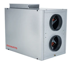
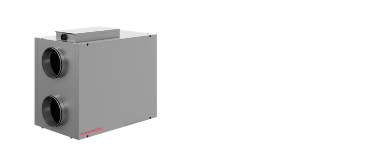
One of the most compact air handling units with counter flow heat exchanger on the market. Optimised design in terms of temperature efficiency, airflow and energy consumption.

In principle, EXHAUSTO VEX units are designed for use in comfort ventilation - i.e. under ordinary operating conditions.
Where ventilation solutions are required for rooms with high air humidity - e.g. due to humidification, we recommend you make a test calculation with one of our calculation programs. If the calculation shows a risk of condensation after the heat exchanger, an assessment must be made whether the operating conditions can be changed, or whether the unit must be modified to allow condensate to drain off. This is particularly relevant for VEX100CF.
Contact EXHAUSTO for advice on this.
| Variants | ECO efficiency level during optimal operating point | Efficiency level requirements | Max. Total efficiency (A-D) (%) | Overload protection |
|---|---|---|---|---|
| VEX330H1 | 78,7N | 62N (2015) | 60,1 % | Built-in |
| VEX330H2 | 73,7N | 62N (2015) | 60,1 % | Built-in |
| Variants | Connection direction | Type of exchanger | Current overload protection |
|---|---|---|---|
| VEX330H1 | Horizontal | Counterflow | Built-in |
| VEX330H2 | Horizontal | Counterflow | Built-in |
| Variants | Control signal with control system | Control signal with third party control system | Fluid temperature (air) | Regulation | Ambient temperature range |
|---|---|---|---|---|---|
| VEX330H1 | Modbus | 0-10 V DC | -40°C ....+40°C | Variable via motor control (MC) | -30°C ....+50°C |
| VEX330H2 | Modbus | 0-10 V DC | -40°C ....+40°C | Variable via motor control (MC) | -30°C ....+50°C |
| Variants | Ø connection (mm) | Weight (kg) | Weight for transport |
|---|---|---|---|
| VEX330H1 | 315 mm | 153 kg | 143 kg (without a removable panel) |
| VEX330H2 | 315 mm | 156 kg | 146 kg (without a removable panel) |
| Variants | Max. airflow (m³/h) | Max. airflow ErP (m³/h) | Minimum airflow |
|---|---|---|---|
| VEX330H1 | 900 m³/h | 830 m³/h | 70 |
| VEX330H2 | 1555 m³/h | 1510 m³/h | 100 |
| Variants | Frequency (Hz) | Max. power of electrical coil 1 (kW) | Max. electrical output of unit (kW) | Voltage (V) | Max. power of electrical coil 2 | Maximum current - unit (A) |
|---|---|---|---|---|---|---|
| VEX330H1 | 50 Hz | 4 kW | 0,6 kW | 1x230 V | 7,8 | 3,1 A |
| VEX330H2 | 50 Hz | 4 kW | 1,2 kW | 1x230 V | 7,8 | 5,3 A |

MECHANICAL PERFORMANCE:
According to DS/EN 1886 and certified by Eurovent:
Strength of the unit casing: D1 (M)
Leakage at -400 Pa negative pressure: L1 (M)
Leakage at +700 Pa positive pressure: L1 (M)
Filter bypass leakage: F9 at negative and positive pressure
Thermal transmission: T2 (M)
Thermal bridging factor: TB3

Cabinets are made from Aluzinc® AZ185 class C4 in accordance with EN/ISO12944-2 and insulated with 50 mm mineral wool. This results in low noise emissions to the surrounding environment/installation room.
The panel design minimises the formation of thermal bridges in the unit.

The motor sections are mounted in vibration dampers, which reduces noise in the ducts and eliminates the need to fit flexible connections between the unit and the duct system.
The motors are of type EC and are extremely efficient. They comply with the requirements of the Ecodesign Directive.

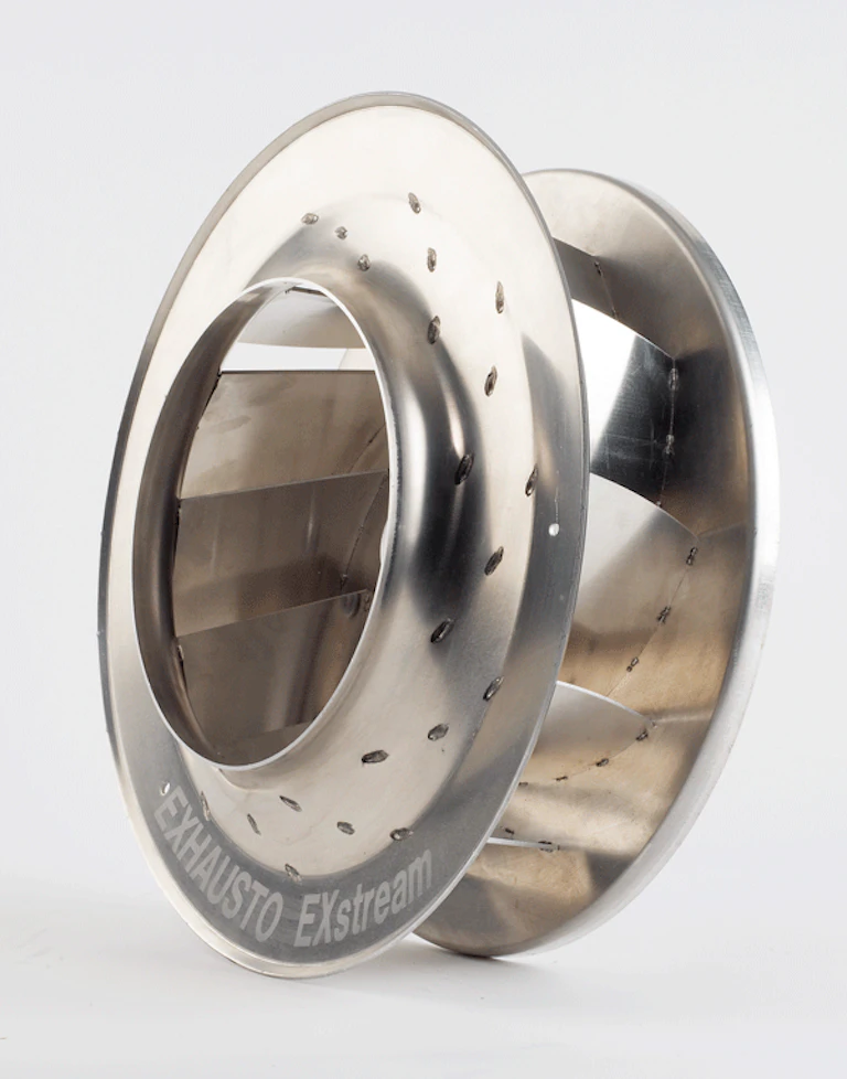
VEX300H is equipped with an optimised centrifugal fan impeller with backwards curved vanes. The impeller design delivers high output with low energy consumption.

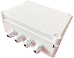
The easily accessible connection box with built-in switch disconnector ensures easy access for connecting and adjusting.

Panel filters are easy to replace and can be ordered as Coarse 85% (M5) or ePM1 55% (F7) in acc. with EN779.
Filter size: 340 x 630 x 96 mm
The side panels on both sides of VEX330H models can be removed (easy access). This allows the unit to function as both a LEFT and RIGHT version.
The unit can also be ordered as an outdoor model. The outdoor unit has a fitted cover that protects it against wind and weather.
The VEX330H is designed with de-icing bypass. If there is a risk of icing, then a certain amount of outdoor air will bypass the heat exchanger and go directly to the after heating coil. This increases the demands on the heating coil’s output. However, it avoids a costly preheating coil. The drawing below is an example of a de-icing situation, where 20% of outdoor air is directed through the bypass damper.
The control system has temperature-controlled frost protection as standard. It is an inexpensive solution and provides sufficient frost-protection in some situations.
A temperature sensor is fitted inside the heat exchanger and if the temperature falls to a pre-set value, de-icing begins. This temperature level is factory set to 0 °C but it can also be changed to a new value via the control system.
Temperature-controlled frost protection triggers the de-icing process even if there is no ice in the heat exchanger.
The control system monitors the actual airflow and also the pressure drop across the heat exchanger. If ice forms in the heat exchanger, the pressure drop across the heat exchanger will increase and when it exceeds a pre-set value, de-icing begins.
Pressure-controlled frost protection only starts de-icing when ice has actually formed, regardless of whether there are sub-zero temperatures.
2 references