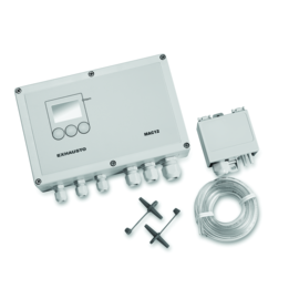
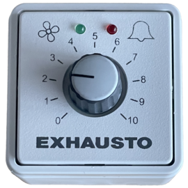
VVR
Wall fan

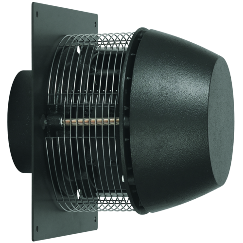
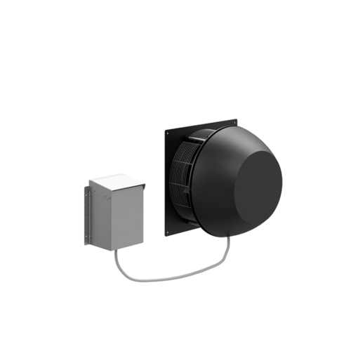
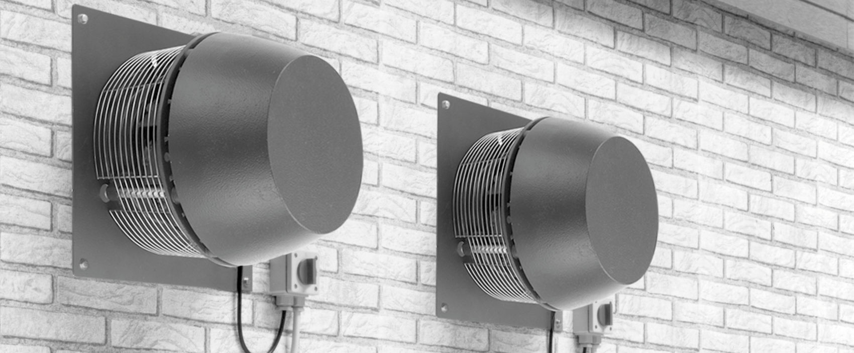
The VVR wall fan is an extraction ventilator manufactured in cast aluminium, ensuring long-term, problem-free operation. The MGO wall penetration is available for this, ensuring simple and correct ventilation.
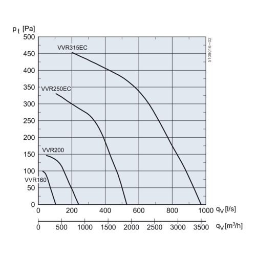
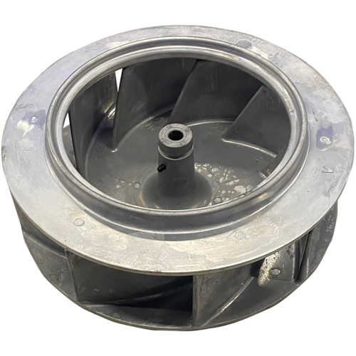
The VVR wall fan has a backward-curved B impeller in aluminium with a radial air exhaust; it can be opened for cleaning. VVR is available in 4 sizes: VVR160, -200, -250, and -315.
MOTORS:
VVR160 and -200 have a single-phase motor, while the other models have an EC motor.
Get an overview of the individual sizes below.
Product advantages
- Radial exhaust
- High corrosion resistance
- Backward curved blades
- High efficiency
- Lower service costs
- Can be used with MGO wall penetration
| References | Max. Total efficiency (A-D) (%) | Ventilation energy class - Average climate | Efficiency level requirements | ECO efficiency level during optimal operating point | EC motor | Nominal speed (RPM) | Overload protection | Engine power (kW) |
|---|---|---|---|---|---|---|---|---|
| VVR16041EC | 29,2 |
C |
62, N(2015) |
64,1 |
1400 |
Integral thermal cutout (TP211) in motor power circuit |
0,04 |
|
| VVR20041EC | 39,6 |
C |
62, N(2015) |
71,6 |
1400 |
Integral thermal cutout (TP211) in motor power circuit |
0,04 |
|
| VVR25041EC2 | 53,5 |
C |
62, N(2015) |
79,4 |
EC motor with integral VSD |
1635 |
Integrated in motor control |
0,18 |
| VVR31541EC2 | 55,1 |
C |
62, N(2015) |
78,0 |
EC motor with integral VSD |
1635 |
Integrated in motor control |
0,37 |
Conditions: > I is the maximum absorbed current throughout the control range - or the full load current if this is larger > P1 is the maximum absorbed power from the mains supply, where P2 is the motor's nominal output. > Stated data for for t = 20°C > Density = 1.2 /m3 > Values are based on the use of a transition piece equivalent to OGSR > Gas temperature: min. -12°C, max. +60° C > Ambient temperature: Max. +40° C > Pressure ratio: < 1,11 > other points in acc. with EC327/2011 - see product instructions
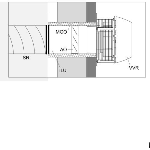
To ease installation an MGO wall duct can be used with the VVR wall fan. The MGO is made from galvanised sheeting with 25 mm insulation against sound and condensation. An integral anti-backdraught shutter is included and the duct can be adjusted to lengths from 210 - 400 mm, to match the thickness of the wall. MGO can be mounted together with diffusor (1), inlet sleeve ILMF and cover flange MGAF as shown below. INSTALLATION SOLUTION 1 If a MGO terminates flush with the internal wall, a covering flange (MGAF) and inlet sleeve (ILMF ) must be fitted before the diffusor is fitted (1). INSTALLATION SOLUTION 2 If the (MGO) is shorter than the wall's thickness, an inlet (ILU) and sleeve (MF) or a spiro tube (SR) must be fitted before the diffusor (1) is fitted. INSTALLATION SOLUTION 3 If there is a long distance between the MGO and the exhaust location, an ILU inlet connected to SR spiral tube must be mounted.

| References | A (mm) | C (mm) | D (mm) | Ø B (mm) | E Ø (mm) | Weight (kg) |
|---|---|---|---|---|---|---|
| VVR16041EC | 235 |
335 |
65 |
275 |
160 |
10 |
| VVR20041EC | 260 |
385 |
65 |
345 |
200 |
13 |
| VVR25041EC2 | 320 |
435 |
75 |
440 |
250 |
22 |
| VVR31541EC2 | 365 |
500 |
75 |
525 |
315 |
29 |
| References | Minimum airflow | Max. airflow (m³/h) |
|---|---|---|
| VVR16041EC | 60 |
370 |
| VVR20041EC | 130 |
860 |
| VVR25041EC2 | 250 |
1900 |
| VVR31541EC2 | 470 |
3360 |
| References | Voltage (V) | Frequency (Hz) | Max. power | Max. current (A) | Engine power (kW) |
|---|---|---|---|---|---|
| VVR16041EC | 1x230 |
50 |
0,022 |
0,2 |
0,04 |
| VVR20041EC | 1x230 |
50 |
0,054 |
0,35 |
0,04 |
| VVR25041EC2 | 1x230 |
50 |
0,18 |
1,2 |
0,18 |
| VVR31541EC2 | 1x230 |
50 |
0,43 |
2,6 |
0,37 |
| Ventilation energy class - Average climate |
|---|
| C |
VVR is made from cast aluminium, giving it a high corrosion resistance (corrosion class C4 in accordance with EN ISO 12944-2). It is painted in black RAL7021.

VVR is an extract fan with a vertical exhaust. The design ensures an optimum air handling solution with minimum noise.

VVR wall fan is ideal for ventilation tasks requiring efficient and economical ventilation. The specially developed centrifugal impeller with backward curved blades ensures high efficiency and low operating costs.
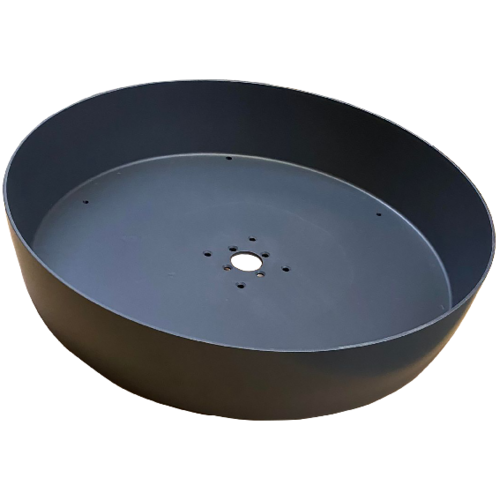
If there is a high level of humidity in the extract air, the VVR wall fan can be ordered with a guide panel. The guide panel ensures that moisture does not run down the wall but is guided away from it.
To ease installation an MGO wall duct can be used with the VVR wall fan. The MGO is made from galvanised sheeting with 25 mm insulation against sound and condensation. An integral anti-backdraught shutter is included and the vent can be adjusted to lengths from 210 - 400 mm, to match the thickness of the wall. The MGO can be mounted together with a diffusor (1) inlet sleeve ILMF and cover flange MGAF as shown below.
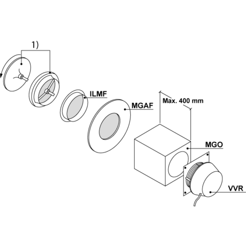
INSTALLATION SOLUTION 1 If a wall duct (MGO) terminates flush with the internal wall, a covering flange (MGAF) and inlet sleeve (ILMF ) must be fitted before the diffusor is fitted (1).
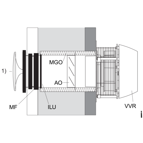
Mounting solution 2 If the MGO is shorter than the thickness of the wall, an inlet (ILU) and sleeve (MF) or spiral pipe (SR) must be installed, to which the diffuser (1) is attached.

INSTALLATION SOLUTION 3 If there is a long distance between the MGO wall duct and the exhaust location, an ILU inlet connected to SR spiral tube must be mounted.
Products and accessories references
Documents
-
VVR, EC Declaration of ConformityCertificates and declarations106 KB
-
VVR with EC motor, EF-Declaration of ConformityCertificates and declarations107 KB
-
VVR MGO mounting and instruction manualInstructions7 MB
-
DIAGRAM FOR DTH16041EC, DTH20041EC, DTV16041EC, DTV20041EC, VVR16041EC, VVR20041EC, BESF14641ECInstructions202 KB

