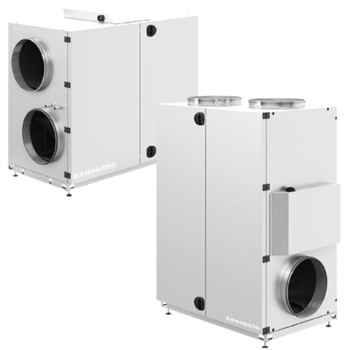
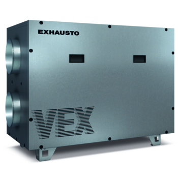
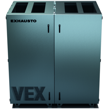
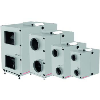
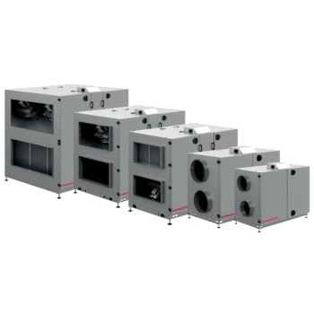
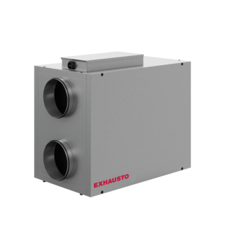
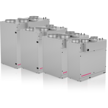
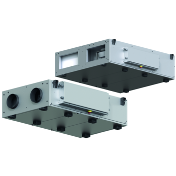
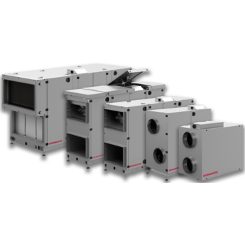
VEX160CF H-V

VEX160CF is available in horizontal and vertical versions

Technical data

Technical data, VEX160CF

Unit data

Min. airflow
1,053 m³/h
Max. airflow
4,680 m³/h
Absorbed power 4,8 kW
Power supply 3 x 400 V + N + PE~ 50 Hz
Max. phase current 15,5 A *
Max. neutral current 23.5 A
Weight
Operation-ready unit 410 kg
For transport into the location 242 kg **
Motor and motor control (MC) data
Motor type EC motor
Motor class in accordance with IEC TS 60034-30-2 IE5 (Ultra Premium Efficiency)
Voltage input 1 x 230 V
Current overload protection Built-in
Regulation Variable via motor control (MC)
Control signal With integrated control system:
Modbus
For third-party control system:
0-10 V DC 
* (power consumption is taken from two phases and is not sinusoidal)
** (excl. doors, heat exchanger and fan units)
 
Heating coils
Electric heating coil (HCE) 14.4 kW
Absorbed power total 19.2 kW
Power supply 3 x 400 V + N + PE~ 50 Hz
Max. phase current 36.5 A
Electric heating coil (HCE) 21.6 kW
Absorbed power total 26.4 kW
Power supply 3 x 400 V + N + PE~ 50 Hz
Max. phase current 46.7 A
Electric heating coil (HCE) 28.8 kW
Absorbed power total 33.6 kW
Power supply 3 x 400 V + N + PE~ 50 Hz
Max. phase current 57.0 A
Water heating coil (HCW)

Test pressure
3000 kPa
Max. operating pressure
1000 kPa
Number of rows of pipes
Qty. 2
Number of circuits
Qty. 5
Face area (H x W)
475 x 760 mm
Pipe connection
DN20 (¾")
Fin spacing
2,1 mm
Weight (without fluid)
9,5 kg
Water content
2,4 l


Fan data

 
Max. total efficiency (A-D) 57.1%
ECO measurement set-up (A-D) A
Efficiency level requirements 62N (2015)
ECO efficiency level during optimal operating point 67.2N

Motor data (optimal operating point)

EC motor With motor controller
Absorbed power 2.36 kW
Airflow 4551 m3/h
Total pressure 1065 Pa
RPM during optimal operating point 3078

Conditions:
- Density = 1.2 kg/m3
- Pressure ratio < 1.11
- other points in acc. with EC327/2011 (see product instructions)

Temperature efficiency

Temperature efficiency, VEX160CF

The temperature efficiency and, to a lesser extent, the SFP/SEL values for a specific air handling unit are closely connected to the heat exchanger itself and depend upon the manufacturer. As suppliers can change from time to time, small changes in the technical data can occur, which is why it is always recommended that you perform a calculation for the particular project using our calculation software, EXselectPRO. 

VEX160CF temperature efficiency

The curve is intended as a guideline, and it is recommended that a calculation be performed using the calculation software EXselectPRO for the individual project.

stiplet streg
Efficiency with condensation:
Extract air = 20°C/55 RH
Outdoor air  = -10°C/50 RH
Balance between supply air/extract air = 1,0
kort-lang-stiplet-streg
Efficiency without condensation with imbalance:
Extract air = 25°C/28 RH
Outdoor air = 5°C/50 RH
Balance between supply air/extract air  = 0,8
fed streg Efficiency without condensation in acc. with EN308:
Extract air = 25°C/28 RH
Outdoor air = 5°C/50 RH
Balance between supply air/extract air = 1,0


Calculation

The temperature efficiency of the VEX units is shown at different airflow ratios, calculated as:


t2.1 = Temperature of outdoor air (fresh air)
t2.2 = Temperature of supply air
t1.1 = Temperature of extract air
Extract air = 25 ºC / 30 % RH
Outdoor air (fresh air) = 5 ºC / 50 % RH
Temperature efficiency is stated in accordance with EN308 for dry heat recovery and is increased by condensation.
Dimensional drawings horizontal

Dimensional drawings, VEX160CF-H

VEX160CF-H - Horizontal, Left (unit dimensions in mm)

Dim VEX160CF HL

 desired spigot location, position A or B, to be specified in order.
*) Allow a height for service in front of the unit equivalent to the unit width.
**) Allow a min. of 300 mm free height for service.


VEX160CF-H - Horizontal,Right (unit dimensions in mm)

Dim VEX160CF HR


1.1 Extract air 1.2 Exhaust air 2.1 Outdoor air 2.2 Supply air

 desired spigot location, position A or B, to be specified in order.
*) Allow a height for service in front of the unit equivalent to the unit width.
**) Allow a min. of 300 mm free height for service.

Dimensional drawings vertical

Dimensional drawings, VEX160CF-V

VEX160CF-V - Vertical, Left (unit dimensions in mm)

Dim VEX160CF VL

 desired spigot location, position A or B, to be specified in order.
*) Allow a height for service in front of the unit equivalent to the unit width.
**) Allow a min. of 300 mm free height for service.


VEX160CF-V - Vertical, Right (unit dimensions in mm)

Dim VEX160CF VR


1.1 Extract air 1.2 Exhaust air 2.1 Outdoor air 2.2 Supply air

 desired spigot location, position A or B, to be specified in order.
*) Allow a height for service in front of the unit equivalent to the unit width.
**) Allow a min. of 300 mm free height for service.

Cooling and heating coils

Cooling and heating coils, VEX160CF

The following cooling and heating coils are suitable for VEX160/VEX160CF

Type Model
CW cooling coil (water)  CW500I
CW065x100U
DX cooling/heating coil DX500

Add all about the product series VEX160CF H-V

CONTACT US TODAY

Get free advice on ventilation products and system solutions


Export Requests:
EXHAUSTO Export
Odensevej 76
DK 5550 Langeskov

Tel +45 6566 1234
E-mail: export@exhausto.dk

Calculation programs

Use EXHAUSTO's free calculation programs for calculating ventilation plant and system solutions

Go to Calculation Programs
Vex overview

VEX Summary

Get a quick overview of our entire range of compact VEX air handling units with heat recovery.

View the VEX summary here