Compact AHU
Compact, energy-efficient and space-saving airhandling units for any application
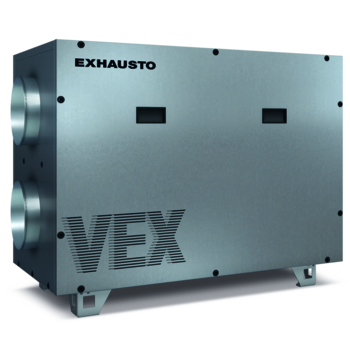
We have a wide range of compact ventilation units, choose between counterflow heat exchangers, crossflow heat exchangers, and rotary heat exchangers, and select from ventilation units in various configurations (horizontal, vertical, top-connected, and ceiling-mounted).
We can always offer a compact and energy-efficient unit for your project. Most models can also be delivered as SPLIT systems for separate transport to the installation site.
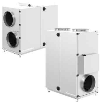
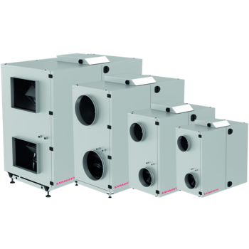
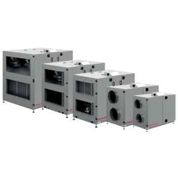
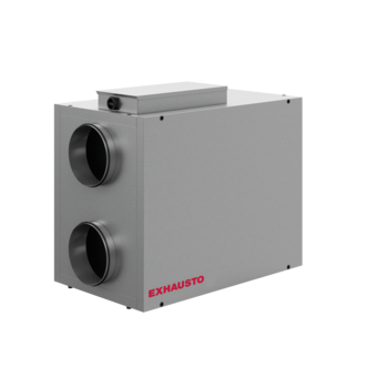
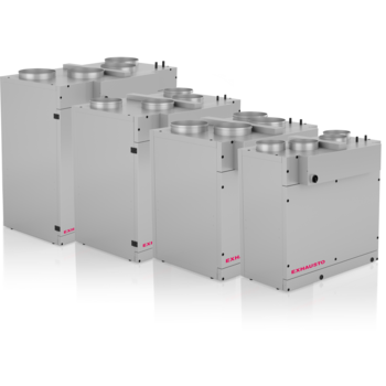
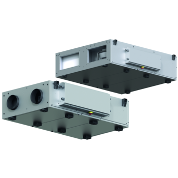
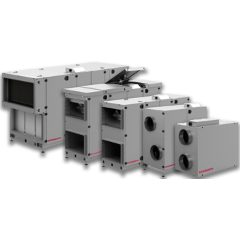
Compact air handling units for many purposes. Our air handling units are available in different designs - horizontal, vertical, ceiling-mounted, and top-mounted units, where the air is discharged from the top of the unit. In the series of air handling units, we can offer both units with rotary exchangers and units with counter-flow exchangers.